Technical Challenge
Water electrolysis for hydrogen production is a central technology in the renewable energy economy. The basic principle involves combining water and electricity to produce hydrogen and oxygen gas. Proton exchange membrane (PEM) water electrolysis operates with liquid water at low temperature and pressure and offers the advantage of relatively high current densities compared to other electrolysis technologies. Several technical challenges arise in the design of PEM electrolyzer stacks,
including (1) achieving homogeneous current distribution to prevent localized material degradation and (2) optimizing liquid flow rate and applied current density to remove gaseous electrolytic products while maintaining acceptably low pressure drops. For these challenges, multiphysics simulation is an excellent tool to improve the design of electrolysis systems by providing detailed and accurate predictions of current and flow distributions during operation.
Veryst Solution
Veryst used COMSOL Multiphysics® to simulate the electric current distribution and multiphase liquid-gas flow in a PEM electrolyzer stack consisting of ten cells. The electric currents are simulated first; the Faradaic currents computed from the current distribution are then used to predict oxygen gas holdup in the anodic compartment.
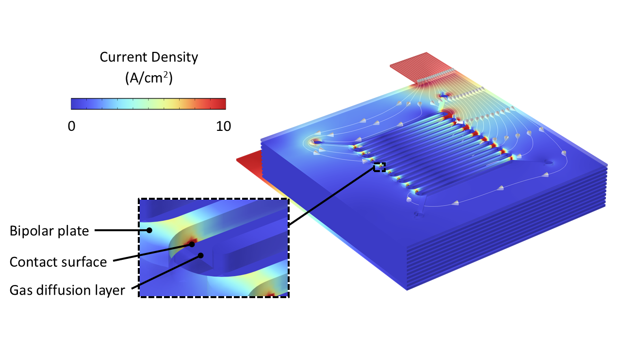
During operation, the highest current densities are concentrated at the junctions between the bipolar plates and gas diffusion layers (GDLs) (Figure 1). These "hot spots" are most susceptible to material degradation over time, which can lead to ohmic inefficiencies due to contact resistance. Moreover, the inhomogeneous distribution of current density at the interface between the GDL and PEM can result in suboptimal gas production due to inefficient transfer between electronic and electrolytic current via electrochemical reactions.
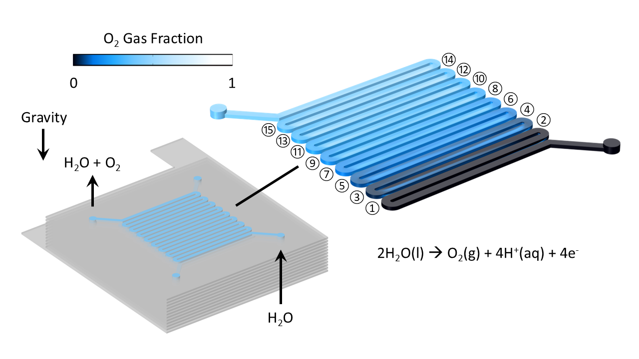
The electric current supplied to the anodic GDL converts liquid water (H2O) to oxygen gas (O2) via the oxygen evolution reaction:
2H2O(l) à O2(g) + 4H+(aq) + 4e-
Gaseous O2 molecules generated at the GDL-PEM interface diffuse through the GDL into the flow channels and are convected to the outlet by H2O flow. The multiphase liquid-gas flow is simulated in Figure 2, showing the generation of O2 gas as liquid flows through a series of channels adjacent to the GDL. The gas holdup in the flow channels leads to reduced liquid flow; gas is carried to the outlet by gravity.
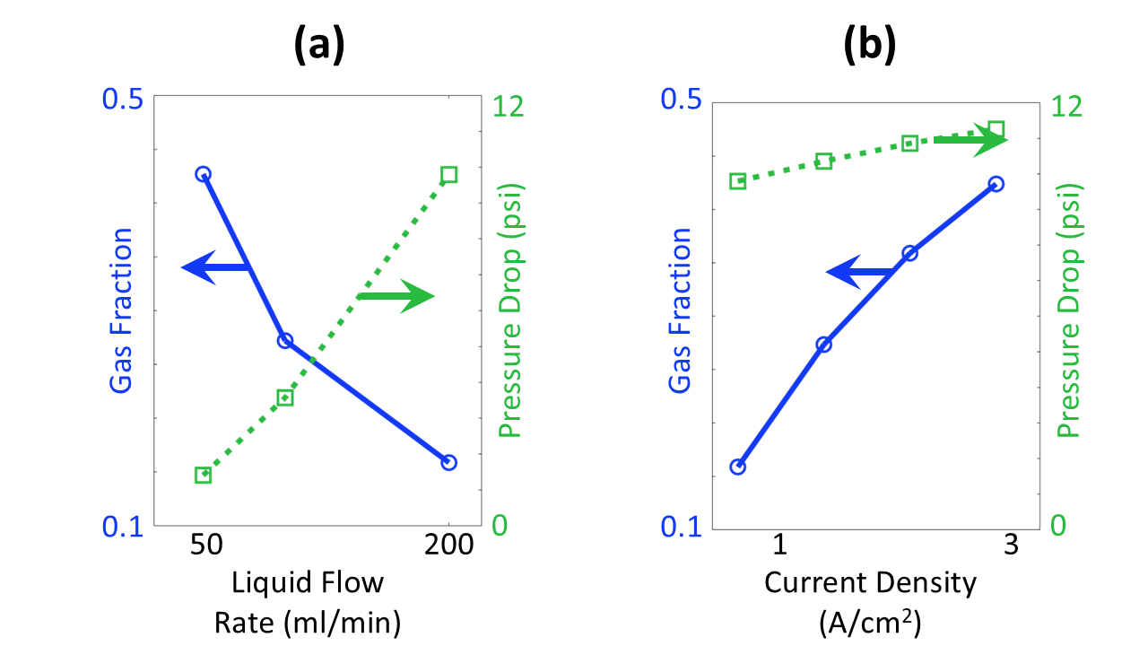
The balance of liquid flow rate and applied current density determines the gas holdup and pressure drop across the electrolysis cell (Figure 3). Higher liquid flow requires stronger driving pressure and generates less gas due to the decreased residence time of H2O reactant molecules (Figure 3a). Higher current densities produces more O2 product molecules, leading to higher gas holdup and higher pressure drop (Figure 3b). Based on these parametric sweeps, Veryst recommended operating the electrolyzer with a liquid flow of 200 ml/min to maintain the cell pressure drop around 10 psi. At this flow rate, operating current densities in the range 1-3 A/cm2 lead to gas fractions below 50%, reducing gas holdup.
Conclusion
Veryst used multiphysics simulations to model the performance of a PEM electrolyzer stack and recommend optimal operating conditions. Our electric current simulations showed that the contact surfaces between conductive elements concentrate the highest density of current and are most suscepible to ohmic loss. Our multiphase flow simulations
predicted the gas fraction and pressure drop in the serial flow network and informed recommendations of optimal flow rate and current density for most-efficient operations. Simulations such as these can be used to improve the design of electrolysis systems to optimize performance prior to pilot- and production-scale manufacturing.