Technical Challenge
Axial permanent magnet couplings (APMCs) consist of two opposing discs, each with an array of permanent magnets backed by a magnetic core. The magnets are magnetized in the axial direction with alternating north and south poles. This arrangement creates an axial flux path through the air gap between the discs, forming a closed, low-reluctance magnetic circuit. The torque applied to the driver is transmitted to the follower by the interaction of magnetic fields generated by the magnets across the air gap. These couplings are used in applications where non-contact torque transfer is required, such as in sealed pumps, compressors, and systems handling hazardous and sensitive fluids.
The torque that can be transmitted using these devices can vary significantly and is determined by geometrical factors such as the size of the air gap, dimension of the magnet, dimension of the magnetic core, type of magnet, material properties of the magnetic core, and more. Due to the complex interaction between these variables, it is difficult to derive a precise analytical formula to design these systems.
Veryst Solution
The electromagnetic simulation experts at Veryst used COMSOL Multiphysics to model the electromagnetic behavior of the APMC with the goal of maximizing transmitted torque. To optimize computational time and resources, our experts modeled only one section of the APMC, and the example model presented here is based on an experimental design from the literature1.
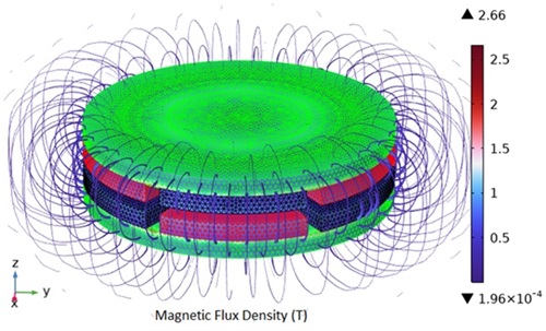
Figure 1 shows the magnetic flux density and the mesh around the magnetic coupling. The streamline plot illustrates the closed magnetic field loop, which extends axially from the driver (transmitter) to the follower.
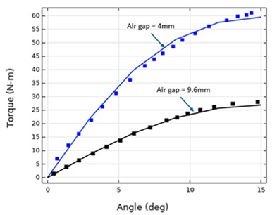
We computed the relationship between torque and angular position, as well as torque and air gap, by parametrically varying these parameters in the model.
The computed torque values were compared with the experimental data from the reference1 for two air gap values, 4 mm and 9.6 mm, as shown in Figure 2.
The simulated torque closely matched the experimental data, demonstrating the accuracy and reliability of the model.
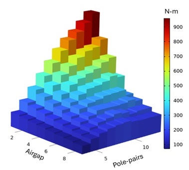
We then explored the effect of two critical design parameters, the number of pole pairs and the air gap, by using the model to compute the electromagnetic torque transfer.
As shown in Figure 3, we achieve maximum torque in the design with the highest number of pole pairs and minimal airgap, indicating the optimal coupling configuration. However, given potential installation constraints or misalignment during operation, the design may need to accommodate larger air gaps.
Torque can decrease significantly as both the airgap and the number of pole pairs increase, making it crucial to evaluate the performance of the device across the entire operational range.
Further studies may include an assessment of the dynamic load performance by analyzing the time-dependent behavior of the device. This would help us better understand how the system performs during torque transmission and under rotor misalignments. Additionally, we may incorporate the nonlinear characteristics of the magnetic core into the simulations, which would refine the model and improve its accuracy. These studies are warranted to ensure the design remains reliable and efficient under real-world operating conditions, particularly in applications with varying loads or misalignment challenges.
Conclusion
Axial permanent magnet couplings offer a highly efficient, non-contact, maintenance-free solution for torque transfer in specialized applications where seals and mechanical contact pose challenges. By optimizing the design parameters such as air gap size, magnetic pole pairs, magnet spacing, and material selection through simulations and modeling, one can tailor the system to meet operational needs across critical applications.
___________________________
1 "Experimental and Theoretical Analysis of Axial Magnetic Coupling under Steady-State and Transient Operation," T. Lubin, S. Mezani, A. Rezzoug, IEEE Transactions on Industrial Electronics, Institute of Electrical and Electronics Engineers (IEEE), Vol. 61, Issue 8, pp. 4356 - 4365, 2013.


